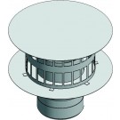
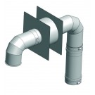
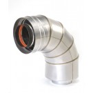
Made from AL29-4C Corrosion Resistant Stainless Steel. 3" Diameter. Kit does include a 90° Bird Screen Termination.
Kit does not include PH20 Adapter. Adapter must be purchased separately.
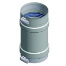
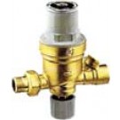
The AutoFill™ automatic filling valve is a pressure reducing valve with
a compensating seat, an inlet filter, a shut-off valve and a check valve.
It is installed on the water inlet piping in sealed heating systems, and
its main function is to maintain the pressure of the system to a preset
value, automatically filling up with water as required. This valve has been
designed as pre-adjustable, which means it can be adjusted at the required
pressure value before charging the system. After installation, during the
filling or topping-off phase, the water feed will stop automatically when the
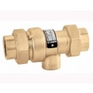
set pressure is reached. There are no levers to flip or valve to close. Preassembled with the backflow preventer, it features an atmospheric vent
which is designed to protect drinking water systems from return flow, caused
by back-siphoning or backpressure, of contaminated fluids. The 573 series
has been specifically certified to standards CSA B64.3 and ASSE 1012.
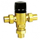
Adjustable, anti-scald thermostatic mixing valve
Series 521
Adjustable Thermostatic and Pressure Balanced Mixing Valve for Point of Distribution in Domestic Water Systems and Radiant Hydronic Heating Systems.
Low-lead Brass Body.
Internal Anti-scale Materials.
Locking Set Point Knob
Max. Working Pressure: 200 PSI
Max. Inlet Temperature 200F
Adjustable Range: 85-150F
ASSE 1017 Listed.
Lead Plumbing Law Compliance:
(0.25% Max. Weighted Average Lead Content)
Lead Plumbing Law Certified by IAPMO R&T.
The thermostatic mixer is used in systems producing domestic hot water or in radiant panel heating systems. Its function is to maintain the temperature of the mixed water supplied to the user constant at the set value when there are variations in the supply conditions of the incoming hot and cold water.
The valve has been specifically certified to ASSE 1017.
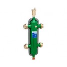
Hydro Separator available in 1"-2" NPT & Sweat Unions. MAX operating pressure: 150 psi. Temperature range with insulation: 32-230 F. Medium: Water & Non-Hazardous Glycol solution. MAX percentage glycol: 50%.
Series 548 Hydro Separator
This device consists of several different functional components, each meet specific
requirements, typical of the circuits used in heating and air-conditioning systems.
• Hydronic separator: To keep connected hydronic circuits totally independent from each other
• Dirt remover: To permit the separation and collection of any impurities present in the circuits. Provided
with a valved connection with discharge piping.
• Automatic air vent valve: For automatic venting of any air contained in the circuits. Provided with a valved connection
for maintenance purposes.
The hydronic separator should be sized according to the maximum flow rate value at 2" 37 the inlet. The selected design value must be the greatest between the primary circuit and the secondary circuit. When a single system contains a primary production circuit, with its own pump, and a secondary user circuit, with one or more distribution pumps, operating conditions may arise in the system whereby the pumps interact, crating abnormal variations in circuit flow rates and pressures. The hydronic separator creates a zone with a low pressure loss, which enables the primary and secondary circuits connected to it to be hydraulically independent of each other; the flow in one circuit does not create a flow in the other if the pressure loss in the common section is negligible. In this case, the flow rate in the respective circuits depends exclusively on the flow rate characteristics of the pumps, preventing reciprocal influence caused by connection in series. Therefore, using a device with these characteristics means that the flow in the secondary circuit only circulates when the relevant pump is on, permitting the system to meet the specific load requirements at that time. When the secondary pump is off, there is no circulation in the secondary circuit; the whole flow rate produced by the primary pump is by-passed through the separator. With the hydronic separator, it is thus possible to have a primary production circuit with a constant flow rate and a secondary distribution circuit with a variable flow rate; these operating conditions are typical of modern heating and cooling systems.