Search results for 'heat exchanger inlet'
-

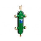
Caleffi 548 Series Hydro Separator-1-1/2" NPT Brass Female Union w/Insulation
Hydro Separator available in 1"-2" NPT & Sweat Unions. MAX operating pressure: 150 psi. Temperature range with insulation: 32-230 F. Medium: Water & Non-Hazardous Glycol solution. MAX percentage glycol: 50%.Series 548 Hydro Separator This device consists of several different functional components, each meet specific requirements, typical of the circuits used in heating and air-conditioning systems. • Hydronic separator: To keep connected hydronic circuits totally independent from each other • Dirt remover: To permit the separation and collection of any impurities present in the circuits. Provided with a valved connection with discharge piping. • Automatic air vent valve: For automatic venting of any air contained in the circuits. Provided with a valved connection for maintenance purposes. The hydronic separator should be sized according to the maximum flow rate value at 2" 37 the inlet. The selected design value must be the greatest between the primary circuit and the secondary circuit. When a single system contains a primary production circuit, with its own pump, and a secondary user circuit, with one or more distribution pumps, operating conditions may arise in the system whereby the pumps interact, crating abnormal variations in circuit flow rates and pressures. The hydronic separator creates a zone with a low pressure loss, which enables the primary and secondary circuits connected to it to be hydraulically independent of each other; the flow in one circuit does not create a flow in the other if the pressure loss in the common section is negligible. In this case, the flow rate in the respective circuits depends exclusively on the flow rate characteristics of the pumps, preventing reciprocal influence caused by connection in series. Therefore, using a device with these characteristics means that the flow in the secondary circuit only circulates when the relevant pump is on, permitting the system to meet the specific load requirements at that time. When the secondary pump is off, there is no circulation in the secondary circuit; the whole flow rate produced by the primary pump is by-passed through the separator. With the hydronic separator, it is thus possible to have a primary production circuit with a constant flow rate and a secondary distribution circuit with a variable flow rate; these operating conditions are typical of modern heating and cooling systems.$578.55 -

Caleffi 548 Series Hydro Separator-1" NPT Brass Female Union w/Insulation
Hydro Separator available in 1"-2" NPT & Sweat Unions. MAX operating pressure: 150 psi. Temperature range with insulation: 32-230 F. Medium: Water & Non-Hazardous Glycol solution. MAX percentage glycol: 50%.Series 548 Hydro Separator This device consists of several different functional components, each meet specific requirements, typical of the circuits used in heating and air-conditioning systems. • Hydronic separator: To keep connected hydronic circuits totally independent from each other • Dirt remover: To permit the separation and collection of any impurities present in the circuits. Provided with a valved connection with discharge piping. • Automatic air vent valve: For automatic venting of any air contained in the circuits. Provided with a valved connection for maintenance purposes. The hydronic separator should be sized according to the maximum flow rate value at 2" 37 the inlet. The selected design value must be the greatest between the primary circuit and the secondary circuit. When a single system contains a primary production circuit, with its own pump, and a secondary user circuit, with one or more distribution pumps, operating conditions may arise in the system whereby the pumps interact, crating abnormal variations in circuit flow rates and pressures. The hydronic separator creates a zone with a low pressure loss, which enables the primary and secondary circuits connected to it to be hydraulically independent of each other; the flow in one circuit does not create a flow in the other if the pressure loss in the common section is negligible. In this case, the flow rate in the respective circuits depends exclusively on the flow rate characteristics of the pumps, preventing reciprocal influence caused by connection in series. Therefore, using a device with these characteristics means that the flow in the secondary circuit only circulates when the relevant pump is on, permitting the system to meet the specific load requirements at that time. When the secondary pump is off, there is no circulation in the secondary circuit; the whole flow rate produced by the primary pump is by-passed through the separator. With the hydronic separator, it is thus possible to have a primary production circuit with a constant flow rate and a secondary distribution circuit with a variable flow rate; these operating conditions are typical of modern heating and cooling systems.$393.41 -

Caleffi 548 Series Hydro Separator-1" Sweat Union w/Insulation
Hydro Separator available in 1"-2" NPT & Sweat Unions. MAX operating pressure: 150 psi. Temperature range with insulation: 32-230 F. Medium: Water & Non-Hazardous Glycol solution. MAX percentage glycol: 50%.Series 548 Hydro Separator This device consists of several different functional components, each meet specific requirements, typical of the circuits used in heating and air-conditioning systems. • Hydronic separator: To keep connected hydronic circuits totally independent from each other • Dirt remover: To permit the separation and collection of any impurities present in the circuits. Provided with a valved connection with discharge piping. • Automatic air vent valve: For automatic venting of any air contained in the circuits. Provided with a valved connection for maintenance purposes. The hydronic separator should be sized according to the maximum flow rate value at 2" 37 the inlet. The selected design value must be the greatest between the primary circuit and the secondary circuit. When a single system contains a primary production circuit, with its own pump, and a secondary user circuit, with one or more distribution pumps, operating conditions may arise in the system whereby the pumps interact, crating abnormal variations in circuit flow rates and pressures. The hydronic separator creates a zone with a low pressure loss, which enables the primary and secondary circuits connected to it to be hydraulically independent of each other; the flow in one circuit does not create a flow in the other if the pressure loss in the common section is negligible. In this case, the flow rate in the respective circuits depends exclusively on the flow rate characteristics of the pumps, preventing reciprocal influence caused by connection in series. Therefore, using a device with these characteristics means that the flow in the secondary circuit only circulates when the relevant pump is on, permitting the system to meet the specific load requirements at that time. When the secondary pump is off, there is no circulation in the secondary circuit; the whole flow rate produced by the primary pump is by-passed through the separator. With the hydronic separator, it is thus possible to have a primary production circuit with a constant flow rate and a secondary distribution circuit with a variable flow rate; these operating conditions are typical of modern heating and cooling systems.$393.41 -

Caleffi 548 Series Hydro Separator-1-1/4" NPT Brass Female Union w/Insulation
Hydro Separator available in 1"-2" NPT & Sweat Unions. MAX operating pressure: 150 psi. Temperature range with insulation: 32-230 F. Medium: Water & Non-Hazardous Glycol solution. MAX percentage glycol: 50%.Series 548 Hydro Separator This device consists of several different functional components, each meet specific requirements, typical of the circuits used in heating and air-conditioning systems. • Hydronic separator: To keep connected hydronic circuits totally independent from each other • Dirt remover: To permit the separation and collection of any impurities present in the circuits. Provided with a valved connection with discharge piping. • Automatic air vent valve: For automatic venting of any air contained in the circuits. Provided with a valved connection for maintenance purposes. The hydronic separator should be sized according to the maximum flow rate value at 2" 37 the inlet. The selected design value must be the greatest between the primary circuit and the secondary circuit. When a single system contains a primary production circuit, with its own pump, and a secondary user circuit, with one or more distribution pumps, operating conditions may arise in the system whereby the pumps interact, crating abnormal variations in circuit flow rates and pressures. The hydronic separator creates a zone with a low pressure loss, which enables the primary and secondary circuits connected to it to be hydraulically independent of each other; the flow in one circuit does not create a flow in the other if the pressure loss in the common section is negligible. In this case, the flow rate in the respective circuits depends exclusively on the flow rate characteristics of the pumps, preventing reciprocal influence caused by connection in series. Therefore, using a device with these characteristics means that the flow in the secondary circuit only circulates when the relevant pump is on, permitting the system to meet the specific load requirements at that time. When the secondary pump is off, there is no circulation in the secondary circuit; the whole flow rate produced by the primary pump is by-passed through the separator. With the hydronic separator, it is thus possible to have a primary production circuit with a constant flow rate and a secondary distribution circuit with a variable flow rate; these operating conditions are typical of modern heating and cooling systems.$474.59 -
Caleffi 548 Series Hydro Separator
Hydro Separator available in 1"-2" NPT & Sweat Unions. MAX operating pressure: 150 psi. Temperature range with insulation: 32-210 F without insulation: 32-250 F. Medium: Water & Non-Hazardous Glycol solution. MAX percentage glycol: 50%.Series 548 Hydro Separator. This device consists of several different functional components, each meet specific requirements, typical of the circuits used in heating and air-conditioning systems. • Hydronic separator: To keep connected hydronic circuits totally independent from each other • Dirt remover: To permit the separation and collection of any impurities present in the circuits. Provided with a valved connection with discharge piping. • Automatic air vent valve: For automatic venting of any air contained in the circuits. Provided with a valved connection for maintenance purposes. The hydronic separator should be sized according to the maximum flow rate value at the inlet. The selected design value must be the greatest between the primary circuit and the secondary circuit. When a single system contains a primary production circuit, with its own pump, and a secondary user circuit, with one or more distribution pumps, operating conditions may arise in the system whereby the pumps interact, creating abnormal variations in circuit flow rates and pressures. The hydronic separator creates a zone with a low pressure loss, which enables the primary and secondary circuits connected to it to be hydraulically independent of each other; the flow in one circuit does not create a flow in the other if the pressure loss in the common section is negligible. In this case, the flow rate in the respective circuits depends exclusively on the flow rate characteristics of the pumps, preventing reciprocal influence caused by connection in series. Therefore, using a device with these characteristics means that the flow in the secondary circuit only circulates when the relevant pump is on, permitting the system to meet the specific load requirements at that time. When the secondary pump is off, there is no circulation in the secondary circuit; the whole flow rate produced by the primary pump is by-passed through the separator. With the hydronic separator, it is thus possible to have a primary production circuit with a constant flow rate and a secondary distribution circuit with a variable flow rate; these operating conditions are typical of modern heating and cooling systems.$393.41 -

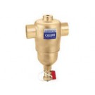
Caleffi Series 546 Dirtcal Dirt Separaters Brass Sweat-1 -1/4"
Dirt Separator. Brass Body. 1/2" NPT Top Thread With Plug For Optional Air Vent, Code 502243A Max. Working Pressure: 150 PSI. Working Temperature Range: 32-250F. Particle Separation Capacity: To 0.2 milIn heating and air conditioning control systems, the circulation of water containing impurities may result in rapid wear and damage to components such as pumps and control valves. It also causes blockages in heat exchangers, heating elements and pipes, resulting in lower thermal efficiency within the system. The dirt separator separates off these impurities, which are mainly made up of particles of sand and rust, collecting them in a large collection chamber, from which they can be removed even while the system is in operation. This device is capable of efficiently removing the smallest particles, with low head loss.$120.18 -
Caleffi Series 546 Dirtcal Dirt Separaters Brass Sweat-1"
Dirt Separator. Brass Body. 1/2" NPT Top Thread With Plug For Optional Air Vent, Code 502243A Max. Working Pressure: 150 PSI. Working Temperature Range: 32-250F. Particle Separation Capacity: To 0.2 milIn heating and air conditioning control systems, the circulation of water containing impurities may result in rapid wear and damage to components such as pumps and control valves. It also causes blockages in heat exchangers, heating elements and pipes, resulting in lower thermal efficiency within the system. The dirt separator separates off these impurities, which are mainly made up of particles of sand and rust, collecting them in a large collection chamber, from which they can be removed even while the system is in operation. This device is capable of efficiently removing the smallest particles, with low head loss.$87.21 -

Caleffi Series 546 Dirtcal Dirt Separaters Brass Sweat
Dirt Separator. Brass Body. 1/2" NPT Top Thread With Plug For Optional Air Vent, Code 502243A Max. Working Pressure: 150 PSI. Working Temperature Range: 32-250F. Particle Separation Capacity: To 0.2 milIn heating and air conditioning control systems, the circulation of water containing impurities may result in rapid wear and damage to components such as pumps and control valves. It also causes blockages in heat exchangers, heating elements and pipes, resulting in lower thermal efficiency within the system. The dirt separator separates off these impurities, which are mainly made up of particles of sand and rust, collecting them in a large collection chamber, from which they can be removed even while the system is in operation. This device is capable of efficiently removing the smallest particles, with low head loss.$87.21 -

Ecobee Smart Thermostat
Ecobee EB-STAT-02 Smart ThermostatConnect. Control. Comfort.
There's a reason why we call this the ecobee Smart Thermostat. For one thing, it's internet enabled through WiFi so that you can easily monitor and manage your home comfort. It's also a smart way to save money and reduce your environmental impact. Genius.
More than just a thermostat, The EB-STAT-02 features Wi-Fi Connectivity to the Internet, Cool Mobile Apps, Easy Web Portal, Live Weather, and a Full Color Screen. Secure Online Web Portal for Remote Management and diagnostics. Free over-the-air Software Upgrades. Gas, Oil, Electric, Boiler, and Heat Pump Compatible. 365 Day Scheduling, 7-Day Programmable, Vacation Programming. Humidifier, dehumidifier and ventilator control. Free Smartphone / Tablet App. Downloadable System Reports.
$298.68 -
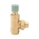
Caleffi Series 519 Differential Pressure Bypass Valve with 3/4" Male Inlet and 3/4" NPTM Outlet.
Caleffi Differential Pressure Bypass ValveCaleffi Series 519 Differential Pressure Bypass Valve with 3/4" Male Inlet and 3/4" NPTM Outlet.$66.22