Search results for 'hydronic water heater'
-
Paloma Recessed Box
FOR PALOMA/WAIWELA OUTDOOR TANKLESS WATER HEATERSThe Recessed Box provides a clean finish to an outdoor installation -- a great look for residential and commercial installs.
If purchased with a tankless water heater, then the Recessed Box is discounted to $275!$300.00 -

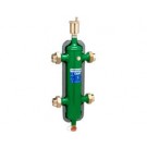
Caleffi 548 Series Hydro Separator-1" NPT Brass Female Union w/Insulation
Hydro Separator available in 1"-2" NPT & Sweat Unions. MAX operating pressure: 150 psi. Temperature range with insulation: 32-230 F. Medium: Water & Non-Hazardous Glycol solution. MAX percentage glycol: 50%.Series 548 Hydro Separator This device consists of several different functional components, each meet specific requirements, typical of the circuits used in heating and air-conditioning systems. • Hydronic separator: To keep connected hydronic circuits totally independent from each other • Dirt remover: To permit the separation and collection of any impurities present in the circuits. Provided with a valved connection with discharge piping. • Automatic air vent valve: For automatic venting of any air contained in the circuits. Provided with a valved connection for maintenance purposes. The hydronic separator should be sized according to the maximum flow rate value at 2" 37 the inlet. The selected design value must be the greatest between the primary circuit and the secondary circuit. When a single system contains a primary production circuit, with its own pump, and a secondary user circuit, with one or more distribution pumps, operating conditions may arise in the system whereby the pumps interact, crating abnormal variations in circuit flow rates and pressures. The hydronic separator creates a zone with a low pressure loss, which enables the primary and secondary circuits connected to it to be hydraulically independent of each other; the flow in one circuit does not create a flow in the other if the pressure loss in the common section is negligible. In this case, the flow rate in the respective circuits depends exclusively on the flow rate characteristics of the pumps, preventing reciprocal influence caused by connection in series. Therefore, using a device with these characteristics means that the flow in the secondary circuit only circulates when the relevant pump is on, permitting the system to meet the specific load requirements at that time. When the secondary pump is off, there is no circulation in the secondary circuit; the whole flow rate produced by the primary pump is by-passed through the separator. With the hydronic separator, it is thus possible to have a primary production circuit with a constant flow rate and a secondary distribution circuit with a variable flow rate; these operating conditions are typical of modern heating and cooling systems.$393.41 -

Caleffi 548 Series Hydro Separator-1-1/4" NPT Brass Female Union w/Insulation
Hydro Separator available in 1"-2" NPT & Sweat Unions. MAX operating pressure: 150 psi. Temperature range with insulation: 32-230 F. Medium: Water & Non-Hazardous Glycol solution. MAX percentage glycol: 50%.Series 548 Hydro Separator This device consists of several different functional components, each meet specific requirements, typical of the circuits used in heating and air-conditioning systems. • Hydronic separator: To keep connected hydronic circuits totally independent from each other • Dirt remover: To permit the separation and collection of any impurities present in the circuits. Provided with a valved connection with discharge piping. • Automatic air vent valve: For automatic venting of any air contained in the circuits. Provided with a valved connection for maintenance purposes. The hydronic separator should be sized according to the maximum flow rate value at 2" 37 the inlet. The selected design value must be the greatest between the primary circuit and the secondary circuit. When a single system contains a primary production circuit, with its own pump, and a secondary user circuit, with one or more distribution pumps, operating conditions may arise in the system whereby the pumps interact, crating abnormal variations in circuit flow rates and pressures. The hydronic separator creates a zone with a low pressure loss, which enables the primary and secondary circuits connected to it to be hydraulically independent of each other; the flow in one circuit does not create a flow in the other if the pressure loss in the common section is negligible. In this case, the flow rate in the respective circuits depends exclusively on the flow rate characteristics of the pumps, preventing reciprocal influence caused by connection in series. Therefore, using a device with these characteristics means that the flow in the secondary circuit only circulates when the relevant pump is on, permitting the system to meet the specific load requirements at that time. When the secondary pump is off, there is no circulation in the secondary circuit; the whole flow rate produced by the primary pump is by-passed through the separator. With the hydronic separator, it is thus possible to have a primary production circuit with a constant flow rate and a secondary distribution circuit with a variable flow rate; these operating conditions are typical of modern heating and cooling systems.$474.59 -

Caleffi 548 Series Hydro Separator-1-1/2" NPT Brass Female Union w/Insulation
Hydro Separator available in 1"-2" NPT & Sweat Unions. MAX operating pressure: 150 psi. Temperature range with insulation: 32-230 F. Medium: Water & Non-Hazardous Glycol solution. MAX percentage glycol: 50%.Series 548 Hydro Separator This device consists of several different functional components, each meet specific requirements, typical of the circuits used in heating and air-conditioning systems. • Hydronic separator: To keep connected hydronic circuits totally independent from each other • Dirt remover: To permit the separation and collection of any impurities present in the circuits. Provided with a valved connection with discharge piping. • Automatic air vent valve: For automatic venting of any air contained in the circuits. Provided with a valved connection for maintenance purposes. The hydronic separator should be sized according to the maximum flow rate value at 2" 37 the inlet. The selected design value must be the greatest between the primary circuit and the secondary circuit. When a single system contains a primary production circuit, with its own pump, and a secondary user circuit, with one or more distribution pumps, operating conditions may arise in the system whereby the pumps interact, crating abnormal variations in circuit flow rates and pressures. The hydronic separator creates a zone with a low pressure loss, which enables the primary and secondary circuits connected to it to be hydraulically independent of each other; the flow in one circuit does not create a flow in the other if the pressure loss in the common section is negligible. In this case, the flow rate in the respective circuits depends exclusively on the flow rate characteristics of the pumps, preventing reciprocal influence caused by connection in series. Therefore, using a device with these characteristics means that the flow in the secondary circuit only circulates when the relevant pump is on, permitting the system to meet the specific load requirements at that time. When the secondary pump is off, there is no circulation in the secondary circuit; the whole flow rate produced by the primary pump is by-passed through the separator. With the hydronic separator, it is thus possible to have a primary production circuit with a constant flow rate and a secondary distribution circuit with a variable flow rate; these operating conditions are typical of modern heating and cooling systems.$578.55 -

Caleffi 548 Series Hydro Separator-1" Sweat Union w/Insulation
Hydro Separator available in 1"-2" NPT & Sweat Unions. MAX operating pressure: 150 psi. Temperature range with insulation: 32-230 F. Medium: Water & Non-Hazardous Glycol solution. MAX percentage glycol: 50%.Series 548 Hydro Separator This device consists of several different functional components, each meet specific requirements, typical of the circuits used in heating and air-conditioning systems. • Hydronic separator: To keep connected hydronic circuits totally independent from each other • Dirt remover: To permit the separation and collection of any impurities present in the circuits. Provided with a valved connection with discharge piping. • Automatic air vent valve: For automatic venting of any air contained in the circuits. Provided with a valved connection for maintenance purposes. The hydronic separator should be sized according to the maximum flow rate value at 2" 37 the inlet. The selected design value must be the greatest between the primary circuit and the secondary circuit. When a single system contains a primary production circuit, with its own pump, and a secondary user circuit, with one or more distribution pumps, operating conditions may arise in the system whereby the pumps interact, crating abnormal variations in circuit flow rates and pressures. The hydronic separator creates a zone with a low pressure loss, which enables the primary and secondary circuits connected to it to be hydraulically independent of each other; the flow in one circuit does not create a flow in the other if the pressure loss in the common section is negligible. In this case, the flow rate in the respective circuits depends exclusively on the flow rate characteristics of the pumps, preventing reciprocal influence caused by connection in series. Therefore, using a device with these characteristics means that the flow in the secondary circuit only circulates when the relevant pump is on, permitting the system to meet the specific load requirements at that time. When the secondary pump is off, there is no circulation in the secondary circuit; the whole flow rate produced by the primary pump is by-passed through the separator. With the hydronic separator, it is thus possible to have a primary production circuit with a constant flow rate and a secondary distribution circuit with a variable flow rate; these operating conditions are typical of modern heating and cooling systems.$393.41 -
Caleffi 548 Series Hydro Separator-1-1/4" Sweat Union w/Insulation
Hydro Separator available in 1"-2" NPT & Sweat Unions. MAX operating pressure: 150 psi. Temperature range with insulation: 32-230 F. Medium: Water & Non-Hazardous Glycol solution. MAX percentage glycol: 50%.Series 548 Hydro Separator This device consists of several different functional components, each meet specific requirements, typical of the circuits used in heating and air-conditioning systems. • Hydronic separator: To keep connected hydronic circuits totally independent from each other • Dirt remover: To permit the separation and collection of any impurities present in the circuits. Provided with a valved connection with discharge piping. • Automatic air vent valve: For automatic venting of any air contained in the circuits. Provided with a valved connection for maintenance purposes. The hydronic separator should be sized according to the maximum flow rate value at 2" 37 the inlet. The selected design value must be the greatest between the primary circuit and the secondary circuit. When a single system contains a primary production circuit, with its own pump, and a secondary user circuit, with one or more distribution pumps, operating conditions may arise in the system whereby the pumps interact, crating abnormal variations in circuit flow rates and pressures. The hydronic separator creates a zone with a low pressure loss, which enables the primary and secondary circuits connected to it to be hydraulically independent of each other; the flow in one circuit does not create a flow in the other if the pressure loss in the common section is negligible. In this case, the flow rate in the respective circuits depends exclusively on the flow rate characteristics of the pumps, preventing reciprocal influence caused by connection in series. Therefore, using a device with these characteristics means that the flow in the secondary circuit only circulates when the relevant pump is on, permitting the system to meet the specific load requirements at that time. When the secondary pump is off, there is no circulation in the secondary circuit; the whole flow rate produced by the primary pump is by-passed through the separator. With the hydronic separator, it is thus possible to have a primary production circuit with a constant flow rate and a secondary distribution circuit with a variable flow rate; these operating conditions are typical of modern heating and cooling systems.$474.59 -

Caleffi 548 Series Hydro Separator-1-1/2" Sweat Union w/Insulation
Hydro Separator available in 1"-2" NPT & Sweat Unions. MAX operating pressure: 150 psi. Temperature range with insulation: 32-230 F. Medium: Water & Non-Hazardous Glycol solution. MAX percentage glycol: 50%.Series 548 Hydro Separator This device consists of several different functional components, each meet specific requirements, typical of the circuits used in heating and air-conditioning systems. • Hydronic separator: To keep connected hydronic circuits totally independent from each other • Dirt remover: To permit the separation and collection of any impurities present in the circuits. Provided with a valved connection with discharge piping. • Automatic air vent valve: For automatic venting of any air contained in the circuits. Provided with a valved connection for maintenance purposes. The hydronic separator should be sized according to the maximum flow rate value at 2" 37 the inlet. The selected design value must be the greatest between the primary circuit and the secondary circuit. When a single system contains a primary production circuit, with its own pump, and a secondary user circuit, with one or more distribution pumps, operating conditions may arise in the system whereby the pumps interact, crating abnormal variations in circuit flow rates and pressures. The hydronic separator creates a zone with a low pressure loss, which enables the primary and secondary circuits connected to it to be hydraulically independent of each other; the flow in one circuit does not create a flow in the other if the pressure loss in the common section is negligible. In this case, the flow rate in the respective circuits depends exclusively on the flow rate characteristics of the pumps, preventing reciprocal influence caused by connection in series. Therefore, using a device with these characteristics means that the flow in the secondary circuit only circulates when the relevant pump is on, permitting the system to meet the specific load requirements at that time. When the secondary pump is off, there is no circulation in the secondary circuit; the whole flow rate produced by the primary pump is by-passed through the separator. With the hydronic separator, it is thus possible to have a primary production circuit with a constant flow rate and a secondary distribution circuit with a variable flow rate; these operating conditions are typical of modern heating and cooling systems.$621.16 -

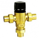
Caleffi Series 521 Mixcal Three Way Mixing Valve Sweat
Caleffi Series 521 Mixcal Three Way Mixing ValveThe thermostatic mixer is used in systems producing domestic hot water or in radiant panel heating systems. Its function is to maintain the temperature of the mixed water supplied to the user constant at the set value when there are variations in the supply conditions of the incoming hot and cold water. The valve has been specifically certified to ASSE 1017.$88.25 -
Caleffi Series 521 Mixcal Three Way Mixing Valve Sweat-3/4"
Adjustable, anti-scald thermostatic mixing valve Series 521 Adjustable Thermostatic and Pressure Balanced Mixing Valve for Point of Distribution in Domestic Water Systems and Radiant Hydronic Heating Systems. Low-lead Brass Body. Internal Anti-scale Materials. Locking Set Point Knob Max. Working Pressure: 200 PSI Max. Inlet Temperature 200F Adjustable Range: 85-150F ASSE 1017 Listed. Lead Plumbing Law Compliance: (0.25% Max. Weighted Average Lead Content) Lead Plumbing Law Certified by IAPMO R&T.The thermostatic mixer is used in systems producing domestic hot water or in radiant panel heating systems. Its function is to maintain the temperature of the mixed water supplied to the user constant at the set value when there are variations in the supply conditions of the incoming hot and cold water. The valve has been specifically certified to ASSE 1017.$88.25 -

Caleffi Series 521 Mixcal Three Way Mixing Valve Sweat-1"
Adjustable, anti-scald thermostatic mixing valve Series 521 Adjustable Thermostatic and Pressure Balanced Mixing Valve for Point of Distribution in Domestic Water Systems and Radiant Hydronic Heating Systems. Low-lead Brass Body. Internal Anti-scale Materials. Locking Set Point Knob Max. Working Pressure: 200 PSI Max. Inlet Temperature 200F Adjustable Range: 85-150F ASSE 1017 Listed. Lead Plumbing Law Compliance: (0.25% Max. Weighted Average Lead Content) Lead Plumbing Law Certified by IAPMO R&T.The thermostatic mixer is used in systems producing domestic hot water or in radiant panel heating systems. Its function is to maintain the temperature of the mixed water supplied to the user constant at the set value when there are variations in the supply conditions of the incoming hot and cold water. The valve has been specifically certified to ASSE 1017.$105.14